- DevLog(블로그) 인프라: build-blog.js (MD→HTML), devlog.css, devlog.js
- DevLog 목록/포스트 페이지 4개 언어 (ko/en/ja/zh)
- 글 2편 작성 + 번역: 관성식vs광학식, 광학식 파이프라인
- 전체 네비게이션에 DevLog 탭 추가 (37+ HTML)
- 메인 팝업(요금제 변경 안내) 제거 (ko/en/ja/zh)
- i18n.js: 언어별 페이지에서 번역 JSON 항상 로드하도록 수정
- 방문자 싸인 이미지 3장 추가 (webp 변환)
- sitemap, i18n JSON, package.json 업데이트

Co-Authored-By: Claude Opus 4.6 (1M context) <noreply@anthropic.com>
27 KiB
| title | description | date | category | thumbnail |
|---|---|---|---|---|
| Complete Anatomy of the Optical Motion Capture Pipeline — From Cameras to Motion Data | An in-depth guide to the entire optical motion capture technical pipeline. We cover camera installation, PoE networking, 2D centroids, calibration, 3D reconstruction, skeleton solving, post-processing, and on-set practical issues in 10 detailed steps. | 2026-04-05 | Motion Capture Technology | images/thumbnail.webp |
When an actor wearing a suit moves in a motion capture studio, the on-screen character follows in real time. It looks simple, but behind the scenes runs a precise technical pipeline: camera hardware → network transmission → 2D image processing → 3D reconstruction → skeleton solving → real-time streaming.
In this article, we dissect the entire pipeline of optical motion capture (based on OptiTrack) step by step.
Step 1: Camera Installation and Placement Strategy
The first step in optical motion capture is deciding where and how to place the cameras.
Placement Principles
- Height: Cameras are typically mounted at 2–3m height, angled about 30 degrees downward
- Layout: Arranged in a ring formation surrounding the capture volume (shooting space)
- Two-tier placement: Alternating cameras at high and low positions improves vertical coverage
- Overlap: Every point within the capture volume must be visible to at least 3 cameras simultaneously. Triangulation requires a minimum of 2, but 3 or more significantly improves accuracy and occlusion resilience
Relationship Between Camera Count and Accuracy
More cameras means:
- Fewer blind spots → reduced probability of occlusion
- More cameras seeing the same marker → improved triangulation accuracy
- Other cameras compensate if some have issues (redundancy)
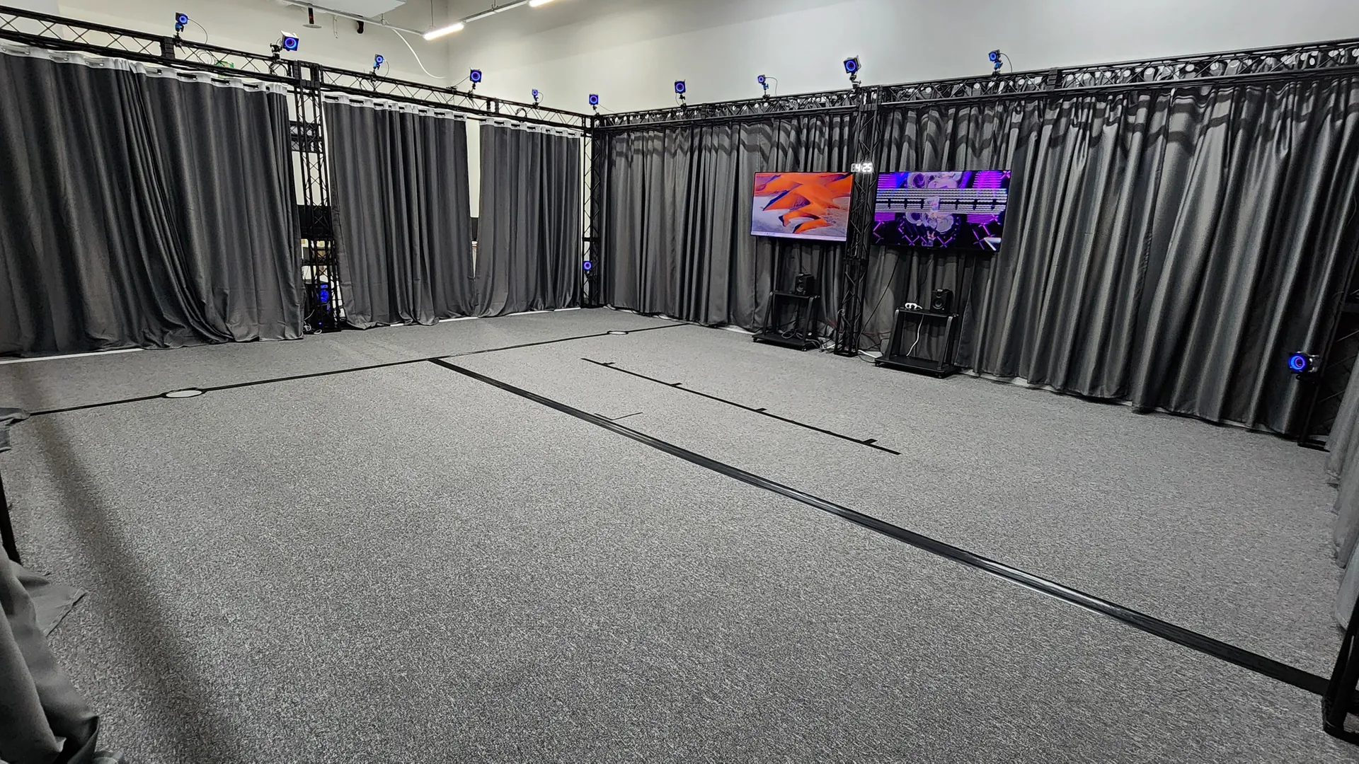
At Mingle Studio, we use OptiTrack Prime 17 × 16 units + Prime 13 × 14 units, a total of 30 cameras arranged in an 8m × 7m space to minimize 360-degree blind spots.
IR Pass Filter — Eyes That See Only Infrared
An IR pass filter (infrared pass filter) is mounted in front of each motion capture camera lens. This filter blocks visible light and allows only infrared wavelengths (around 850nm) to pass through. This eliminates interference from fluorescent lights, sunlight, monitor glow, and other ambient lighting, allowing the camera to detect only marker light reflected from IR LEDs.
This filter is also the reason the studio lighting doesn't need to be completely turned off. However, direct sunlight or lighting with strong IR components can still cause interference, so studios use lighting with minimal IR emission.
Frame Synchronization — How 30 Cameras Shoot Simultaneously
For accurate triangulation, all cameras must trigger their shutters at exactly the same moment. If each camera captures at different timings, the position of fast-moving markers would vary between cameras, making 3D reconstruction inaccurate.
OptiTrack uses a hardware synchronization (Hardware Sync) method. One camera is designated as the Sync Master, generating timing signals, while the remaining cameras expose simultaneously in sync with this signal.
- Ethernet cameras (Prime series): The sync signal is embedded in the Ethernet connection itself or delivered through OptiTrack's eSync hub. No separate sync cable is needed.
- USB cameras (Flex series): Cameras are connected via dedicated sync cables in a daisy chain.
The precision of this synchronization is at the microsecond (μs) level, meaning all 30 cameras capture at virtually the exact same moment.
Step 2: PoE — Power and Data Through a Single Cable
What Is PoE (Power over Ethernet)?
OptiTrack Prime series cameras connect via PoE (Power over Ethernet). This technology delivers both power and data simultaneously through a single standard Ethernet cable (Cat5e/Cat6).

Technical Standards
| Standard | Max Power | Notes |
|---|---|---|
| IEEE 802.3af (PoE) | 15.4W per port | Sufficient for standard motion capture cameras |
| IEEE 802.3at (PoE+) | 25.5W per port | For high-frame-rate cameras or those with high IR LED output |
OptiTrack cameras typically consume around 5–12W, well within the PoE standard range.
Network Topology
Cameras are connected in a star topology. Each camera connects 1:1 to an individual port on the PoE switch. Daisy chaining (serial connection) is not used.
For 30 cameras, you would combine a 24-port + 8-port PoE+ switch or use a 48-port switch. When selecting a switch, you must verify the total PoE power budget (e.g., 30 cameras × 12W = 360W).
Advantages of PoE
- One cable does it all — no need for separate power adapters for each ceiling-mounted camera
- Clean installation — cable count is cut in half, simplifying installation and management
- Centralized power management — cameras can be collectively powered ON/OFF from the switch
Step 3: What the Camera Sends — 2D Centroids
Understanding what data is transmitted from cameras to the PC is the key to the pipeline.

Camera Internal Processing
Each OptiTrack camera has an infrared (IR) LED ring mounted around the camera lens. These LEDs emit infrared light, which is reflected back toward the camera by retroreflective markers attached to the actor's body. The camera sensor captures this reflected light as a grayscale IR image.
The important point here is that the camera does not send this raw image directly to the PC. The camera's internal processor handles it first:
1. Thresholding Only pixels above a certain brightness threshold are kept; the rest are discarded. Since only markers reflecting infrared light appear bright, this process separates markers from the background.
2. Blob Detection Clusters of bright pixels (blobs) are recognized as individual marker candidates.
3. 2D Centroid Calculation The precise center point (centroid) of each blob is calculated with sub-pixel precision (approximately 0.1 pixels). This uses a weighted average method where the brightness of each pixel within the blob serves as the weight.
Data Transmitted to the PC
In the default tracking mode, what the camera sends to the PC is 2D centroid data:
- (x, y) coordinates + size information for each marker candidate
- Extremely small data — only a few hundred bytes per frame per camera
Thanks to this small data volume, 40+ cameras can operate on a single Gigabit Ethernet connection. Raw grayscale images can also be transmitted (for debugging/visualization), but this requires several MB/s per camera and is not used during normal tracking.
In other words, the camera is not "a device that captures and sends video" but rather closer to "a sensor that calculates marker positions and sends only coordinates."
You might wonder — why are motion capture cameras so expensive compared to regular cameras? The answer lies in the process described above. Regular cameras simply send the captured footage as-is, but motion capture cameras have a dedicated onboard processor that performs thresholding, blob detection, and sub-pixel centroid calculation in real time at 240–360 frames per second. Each camera essentially contains a small computer dedicated to image processing.
Step 4: Calibration — Aligning the Camera Eyes
There is a mandatory process before 3D reconstruction can happen. The software must determine each camera's exact position, orientation, and lens characteristics — this is calibration.

Wanding — Scanning the Space
An operator walks through the entire capture volume while waving a calibration wand — a rod with LEDs or markers attached. Since the distances between the wand's markers are precisely known, when each camera captures the wand over thousands of frames, the software can calculate:
- Intrinsic Parameters — characteristics unique to the camera lens, such as focal length and lens distortion coefficients
- Extrinsic Parameters — the camera's exact position and orientation in 3D space
This calculation uses an optimization algorithm called Bundle Adjustment. It simultaneously optimizes all camera parameters based on thousands of 2D observation data points.
Ground Plane Setup
After wanding, an L-shaped calibration frame (Ground Plane) is placed on the floor. Three or more markers on this frame define the floor plane and coordinate origin:
- Where (0, 0, 0) is (the origin)
- Which directions are the X, Y, Z axes
- The height reference of the floor plane
Once calibration is complete, the software can convert any camera's 2D coordinates into an accurate 3D ray.
Calibration Quality
Motive software displays the reprojection error for each camera after calibration. The smaller this value (typically 0.5px or below), the more accurate the calibration. Cameras with large errors are repositioned or recalibrated.
Step 5: 2D → 3D Reconstruction (Triangulation)
Let's examine how the 2D centroids arriving at the PC are converted into 3D coordinates.
Triangulation Principle
- Utilizing each camera's exact 3D position, orientation, and lens characteristics obtained through calibration
- Casting a ray from the camera's 2D centroid coordinate — a straight line extending from the camera position through the centroid direction into 3D space
- The point where rays from 2 or more cameras viewing the same marker intersect is the marker's 3D coordinate
In Reality, Rays Don't Intersect Perfectly
Due to noise, lens distortion, calibration errors, and other factors, rays almost never meet at a single exact point. That's why Least Squares Optimization is used:
- Calculates the 3D coordinate where the sum of distances to all rays is minimized
- The distance between each ray and the reconstructed 3D point is called the residual
- Smaller residuals mean better reconstruction quality — in a well-calibrated OptiTrack system, sub-millimeter residuals (below 0.5mm) can be expected
Impact of Camera Count
| Number of cameras seeing the marker | Effect |
|---|---|
| 2 | 3D reconstruction possible (minimum requirement) |
| 3 | Improved accuracy + tracking maintained even if 1 camera is occluded |
| 4 or more | High accuracy + strong occlusion resilience |
Step 6: Marker Identification and Labeling
Marker Suit and Marker Placement
To turn 3D reconstruction into meaningful motion data, markers must be attached at precise locations on the body.
Marker Specifications
- Diameter: Typically 12–19mm spherical retroreflective markers
- Material: Foam/plastic spheres coated with 3M retroreflective tape
- Attachment: Velcro, double-sided tape, or pre-mounted on dedicated marker suits
Markerset Standards The number and placement of markers follow standardized markerset specifications:
- Baseline (37 markers) — OptiTrack's default full-body markerset. Covers upper body, lower body, and head; the most commonly used for game/video motion capture
- Baseline + Fingers (~57 markers) — Extended version adding approximately 20 finger markers
- Helen Hayes (~15–19 markers) — Medical/gait analysis standard. A minimal markerset focused on the lower body
Markers are placed at anatomical landmarks where bones protrude (acromion, lateral epicondyle, anterior superior iliac spine, etc.). These locations most accurately reflect bone movement through the skin and minimize skin artifact.
After 3D reconstruction, each frame produces a cloud of unnamed 3D points (Point Cloud). The process of determining "is this point the left knee marker or the right shoulder marker?" is labeling.

Labeling Algorithms
Template Matching Based on the geometric arrangement of the markerset defined during calibration (e.g., the distance between knee and ankle markers), the current frame's 3D points are compared against the template.
Predictive Tracking Based on velocity and acceleration from previous frames, the software predicts where each marker will be in the next frame and matches it to the nearest 3D point.
Marker Swap Problem
When two markers pass very close to each other, the software may swap their labels — a phenomenon where labels are exchanged. This is one of the most common artifacts in optical mocap.
Solutions:
- Manually correct labels in post-processing
- Design marker placement to be asymmetric for easier differentiation
- Use active markers — each marker emits a unique infrared pattern, enabling hardware-level identification and completely eliminating swaps
Passive vs Active Markers
| Category | Passive Markers (Reflective) | Active Markers (Self-emitting) |
|---|---|---|
| Principle | Reflects light from camera IR LEDs | Each marker emits a unique IR pattern |
| Identification | Software-based (swap possible) | Hardware-based (no swaps) |
| Advantages | Lightweight, inexpensive, easy to attach | Auto-identification, no labeling errors |
| Disadvantages | May require post-processing labeling | Heavier, requires battery/power |
In most entertainment/VTuber production environments, passive markers are primarily used. They are lightweight and comfortable, and software performance is good enough that automatic labeling works well in most situations.
Step 7: Skeleton Solving — From Points to a Skeletal Structure
This step maps labeled 3D markers to a human skeleton structure.
Pre-Calibration
Before shooting, the actor strikes a T-pose (arms outstretched), and the software calculates bone lengths (arm length, leg length, etc.) and joint positions based on marker locations.
This is followed by a ROM (Range of Motion) capture.
 Through various movements such as arm circles, knee bends, and torso twists, the software precisely calibrates joint center points and rotation axes.
Real-Time Solving
During capture, for every frame:
- Receives labeled 3D marker coordinates
- Calculates the 3D position and rotation of each joint based on marker positions
- Algorithms such as Inverse Kinematics compute a natural skeletal pose
- Result: Translation + Rotation data for all joints across the timeline
Rigid Body Tracking (Prop Tracking)
By attaching 3 or more markers in an asymmetric pattern to props like swords, guns, or cameras, the software recognizes the marker cluster as a single rigid body, enabling 6DOF (3 axes of position + 3 axes of rotation) tracking.
Step 8: Real-Time Streaming and Data Output
Real-Time Streaming

OptiTrack Motive delivers solved data to external software in real time:
- NatNet SDK — OptiTrack's proprietary protocol, UDP-based low-latency transmission
- VRPN — A standard protocol in the VR/mocap field
This enables real-time character animation in Unity, Unreal Engine, MotionBuilder, and more. VTuber live broadcasts are possible thanks to this real-time streaming.
Recorded Data Output Formats
| Format | Use Case |
|---|---|
| FBX | Skeleton + animation data, compatible with game engines/DCC tools |
| BVH | Hierarchical motion data, primarily used for retargeting |
| C3D | Raw 3D marker data, biomechanics/research standard |
Step 9: Post-Processing — Refining the Data

Data from real-time capture can sometimes be used as-is, but most professional work involves a post-processing stage.
Gap Filling
This fills gaps where markers temporarily disappeared due to occlusion using interpolation.
- Linear interpolation — Simply connects the frames before and after with a straight line. Suitable for short gaps
- Spline interpolation — Fills with smooth curves. Better for maintaining natural movement
- Pattern-based interpolation — References data from other takes of the same repeated movement
The longer the gap, the less accurate the interpolation, which is why minimizing occlusion during shooting is most important.
Smoothing and Filtering
Captured data may contain subtle jitter (high-frequency noise). To remove this:
- Butterworth filter — A low-pass filter that removes noise above a specified frequency
- Gaussian smoothing — Reduces jitter using a weighted average of surrounding frames
However, excessive smoothing can cause loss of detail and impact in the motion, so the strength must be set appropriately to avoid blurring sharp movements like sword swings.
Marker Swap Correction
This involves finding sections where marker swaps (described in Step 6) occurred and manually correcting the labels. In Motive, you can visually inspect and correct marker trajectories on the timeline.
Retargeting
The process of applying captured skeleton data to a character with different proportions. For example, to apply motion data from a 170cm actor to a 3m giant character or a 150cm child character, joint rotations must be preserved while bone lengths are recalculated to match the target character. MotionBuilder, Maya, Unreal Engine, and others provide retargeting functionality.
Step 10: Common On-Set Issues and Solutions
Even seemingly perfect optical mocap encounters real-world challenges on set.
Stray Reflections
Infrared light reflecting off objects other than markers creates ghost markers — false marker detections.
- Causes: Metal surfaces, shiny clothing, glasses, watches, floor reflections, etc.
- Solution: Cover reflective surfaces with matte tape, or use masking in Motive to tell the software to ignore those areas
Marker Detachment
Markers may fall off the suit or shift position during intense movements.
- Solution: Carefully check marker attachment before shooting; for vigorous motion capture, combine Velcro + double-sided tape for stronger adhesion
- It's also important to periodically monitor marker condition during sessions
Clothing Restrictions
Actors should ideally wear light-colored, matte-material clothing during capture. Black doesn't affect marker reflection, but shiny materials or loose clothing can cause unstable marker positions or stray reflections. Wearing a dedicated mocap suit is the most reliable option.
Calibration Maintenance
Calibration can gradually drift due to temperature changes within the capture volume, camera vibrations, or minor tripod shifts. For extended shooting sessions, it's recommended to recalibrate midway, or use Motive's Continuous Calibration feature for real-time correction during capture.
Latency — How Long From Movement to Screen?
Here is the time breakdown for each stage of the pipeline.
| Stage | Duration |
|---|---|
| Camera exposure (at 240fps) | ~4.2ms |
| Camera internal processing (centroid calculation) | ~0.5–1ms |
| Network transmission (PoE → PC) | < 1ms |
| 3D reconstruction + labeling | ~1–2ms |
| Skeleton solving | ~0.5–1ms |
| Streaming output (NatNet) | < 1ms |
| Total end-to-end latency | Approx. 8–14ms (at 240fps) |
At 360fps, the exposure time decreases, making latencies below 7ms achievable. This level of latency is imperceptible to humans, enabling natural real-time response even in VTuber live broadcasts.
Note: Most of the latency comes from the camera exposure time (frame period). This is why higher frame rates result in lower latency.
Full Pipeline Summary
30 cameras arranged in a ring, IR pass filters detect infrared only, hardware sync at μs precision
Single Cat6 cable carries power + data, star topology connection to switch
IR LED emission → marker reflection received → thresholding → blob detection → sub-pixel centroid calculation → coordinates transmitted
Wanding to determine camera intrinsic/extrinsic parameters, ground plane to define coordinate system
Ray intersection from multiple cameras' 2D coordinates + least squares optimization to reconstruct 3D coordinates
Template matching + predictive tracking to assign marker names to each 3D point
Based on T-pose + ROM calibration, inverse kinematics to calculate joint positions and rotations
Real-time transmission to Unity/Unreal/MotionBuilder via NatNet/VRPN, recording in FBX/BVH/C3D
Gap filling · smoothing · marker swap correction · retargeting
Applied to game cinematics · VTuber live · video content (total latency approx. 8–14ms)
The camera does not send raw footage to the PC — instead, the camera calculates marker coordinates internally and sends only those, while the PC reconstructs them in 3D and maps them to a skeleton. This is the core principle of optical motion capture.
Frequently Asked Questions (FAQ)
Q. How is an optical motion capture camera different from a regular camera?
Regular cameras capture full-color video, but motion capture cameras are specialized for the infrared (IR) spectrum. They illuminate markers with IR LEDs, detect only reflected light, and internally calculate the markers' 2D coordinates, transmitting only coordinate data to the PC.
Q. Is there a length limit for PoE cables?
According to the Ethernet standard, PoE cables support a maximum of 100m. Most motion capture studios easily fall within this range.
Q. Is a higher camera frame rate always better?
Higher frame rates are advantageous for fast motion tracking and lower latency, but they increase data throughput and may reduce camera resolution. Generally, 120–240fps is sufficient for VTuber live and game motion capture, while 360fps or higher is used for ultra-high-speed motion analysis in sports science and similar fields.
Q. How often do marker swaps occur?
If the markerset is well-designed and there are enough cameras, swaps during real-time capture are rare. However, the probability increases during fast movements or when markers are close together (such as hand clasping), and these sections are corrected in post-processing.
Q. If 2 cameras are enough for triangulation, why install 30?
Two cameras is merely the theoretical minimum. In practice, you must account for occlusion (marker obstruction), accuracy variations based on camera angle, and redundancy. With 30 cameras deployed, every marker is always seen by multiple cameras, enabling stable and accurate tracking.
Q. How often does calibration need to be done?
Typically, calibration is performed once at the start of each shooting day. However, during extended sessions, calibration can drift due to temperature changes or minor camera movement, so recalibration is recommended during 4–6 hour continuous shoots. Using OptiTrack Motive's Continuous Calibration feature allows real-time correction even during capture.
Q. Is it not allowed to wear shiny clothing?
Because motion capture cameras detect infrared reflections, shiny materials (metal decorations, sequins, glossy synthetic fabrics, etc.) can reflect infrared light and create ghost markers. Wearing a dedicated mocap suit or comfortable clothing made of matte materials is best.
If you have further questions about the technical structure of optical motion capture, feel free to ask on our contact page. If you'd like to experience it firsthand at Mingle Studio, check out our services page.